 Chiral Shape
Projection studies
Turn a solid, fold its shadow, and measure the match.
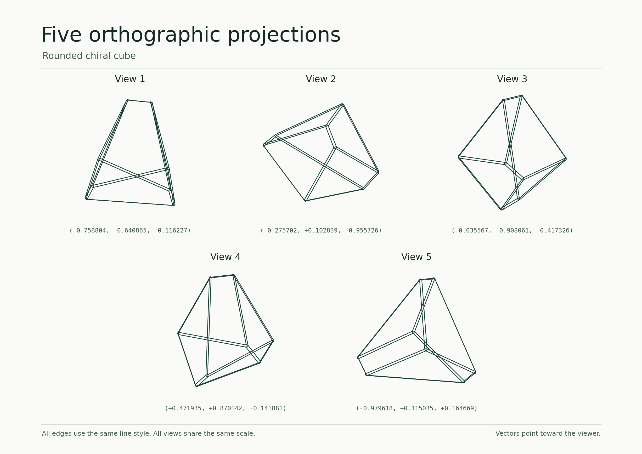
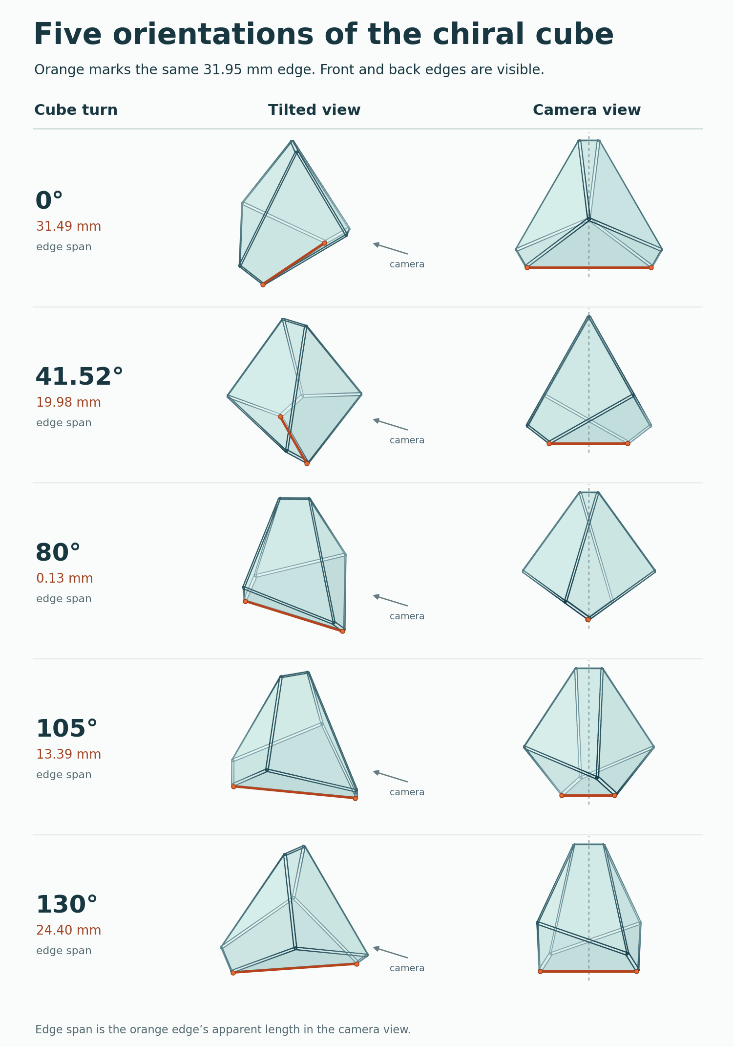
An orthographic camera keeps the horizontal and vertical coordinates and drops depth. The silhouette is the filled shadow. A transparent wireframe draws every recorded edge, so front and back lines can share the same spot on screen.
Rounded chiral cube
A handed solid can still cast a shadow that nearly matches across a fold.
Infinitely many angles give the cube a near-mirror outline. The exact contour count remains open.
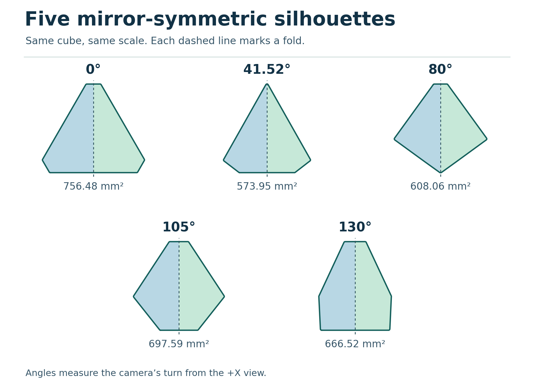
Why the fold survives a turn
Keep a half-turn axis upright and look perpendicular to it. The half-turn keeps height and reverses both left and right and front and back. The camera drops the front-to-back reversal, leaving a left-to-right reflection.
What the measurement means
Measure the distance from each reflected point to the nearest original point, and check both directions. The largest distance is the mirror gap. Here the eight core corners match their half-turned partners to within 0.00000060 mm.
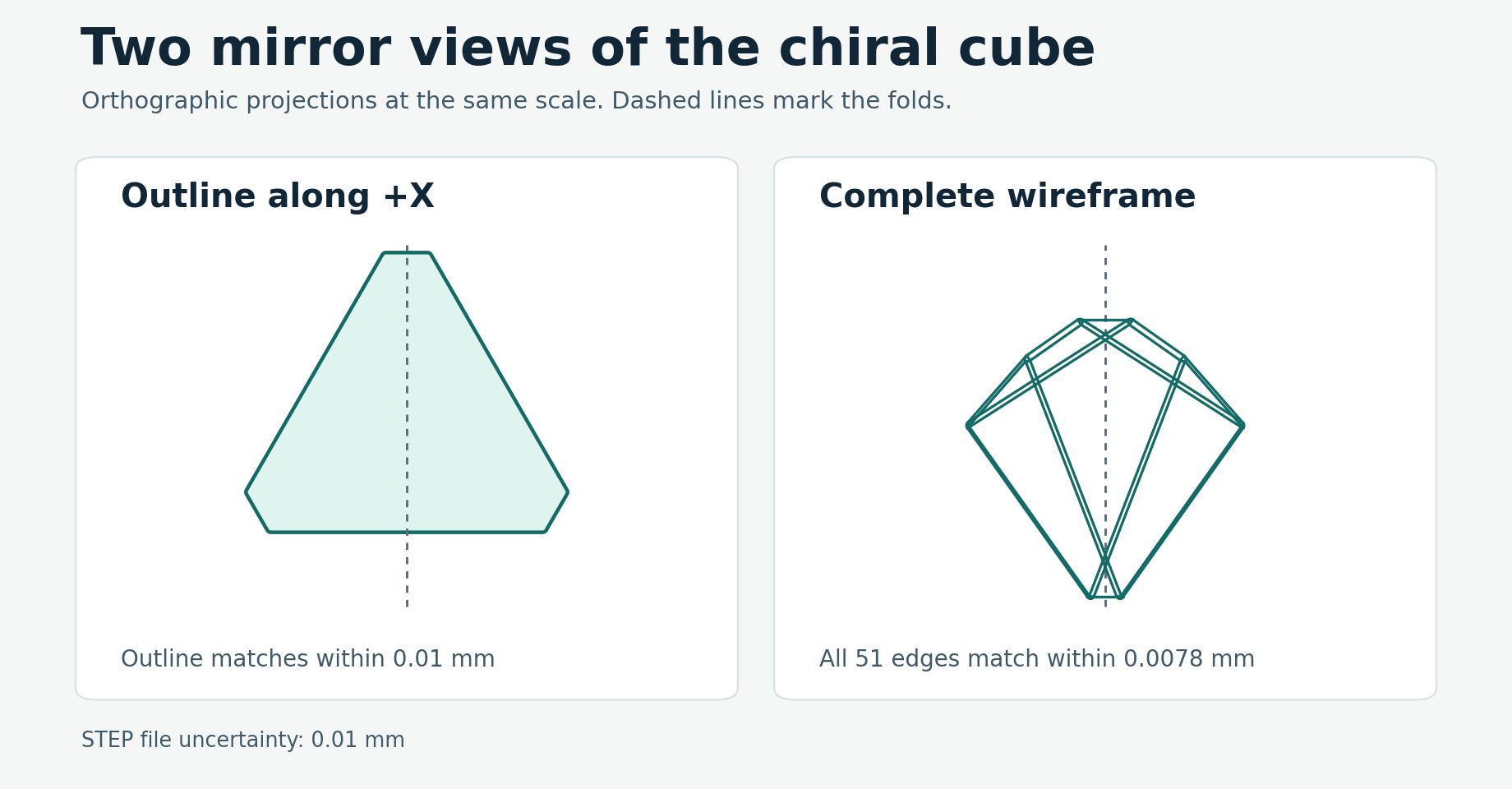
Camera directions and the exact wireframe proof
The +X sightline points from the solid toward the camera along (1, 0, 0). Its screen up is approximately (0, 0.920469, −0.390816). Record other angles by turning +X around this upright axis while staying perpendicular to it.
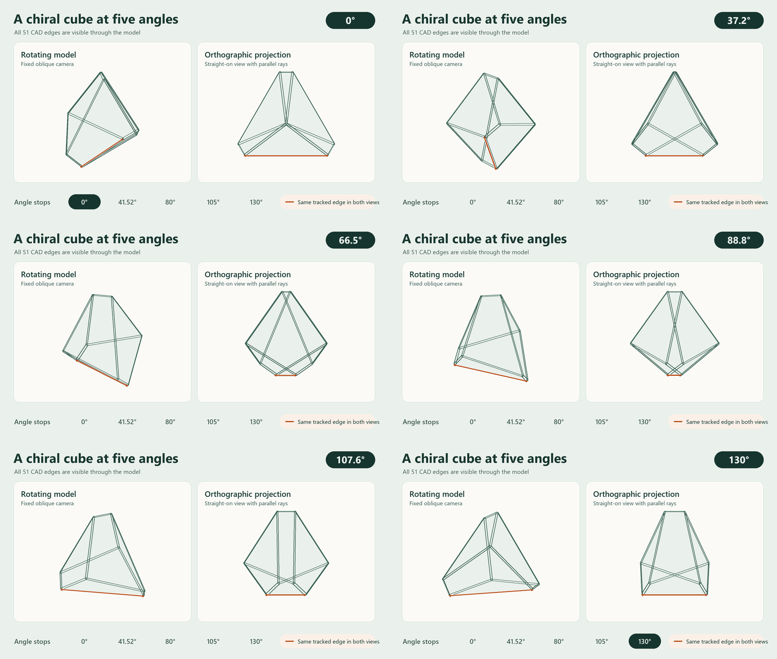
The all-edge near-match uses camera direction (0.34777182, −0.93060115, −0.11417640) and screen up (0, 0.12177787, −0.99255738). Both fold lines pass through the screen projection of (17.51735887, −0.00000003, −0.00000040) mm. At +X, a CAD seam in the all-edge drawing misses its reflection by about 0.104 mm.
A circular arc viewed at an angle lies on an ellipse. A mirror of the whole curve must also mirror the ellipse center. Eight center groups supply at least one genuine ellipse each at every angle. The exact certificate checks all 764 ways to pair separated centers and all 28 directions where center pairs can overlap, including their small neighborhoods. It excludes a perfect fold of the literal 51-edge STEP wireframe at every angle.
The exact zero-gap question for the outer contour alone remains open here. The STEP file declares a connectivity uncertainty of 0.01 mm. The reported gaps describe the recorded geometry.
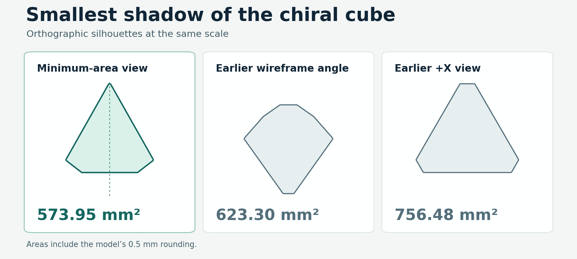
How the cube area minimum covers all angles
The rounded cube is modeled by a convex core with a 0.5 mm radius offset. The projection is a polygon expanded by a disk. Its area is A + rP + πr², where A and P are the core shadow’s area and perimeter. At the minimum they are 525.0523 mm² and 96.2241 mm.
The six planar faces divide the sphere of viewing directions into 32 regions with fixed contributing faces and outline edges. Supporting bounds on area and projected edge lengths cover every region. The minimizing sightline is approximately ±(0.748730168, 0.259062087, 0.610155694). Either sign gives the same area.
Lesson in text
Parallel rays transfer points to a flat screen and remove depth. At +X the cube folds along the projected vertical axis. Drawing every CAD edge reveals a seam gap in that same view.
Under projection, a circular edge becomes an ellipse unless viewed edge-on. A fold has to mirror the centers of those ellipses. Checking 764 separated pairings and 28 overlap directions rules out exact equality for the wireframe. An angled view brings all 51 curves nearly into alignment.
Double Bowl
A triangulated model reveals which details survive the same fold.
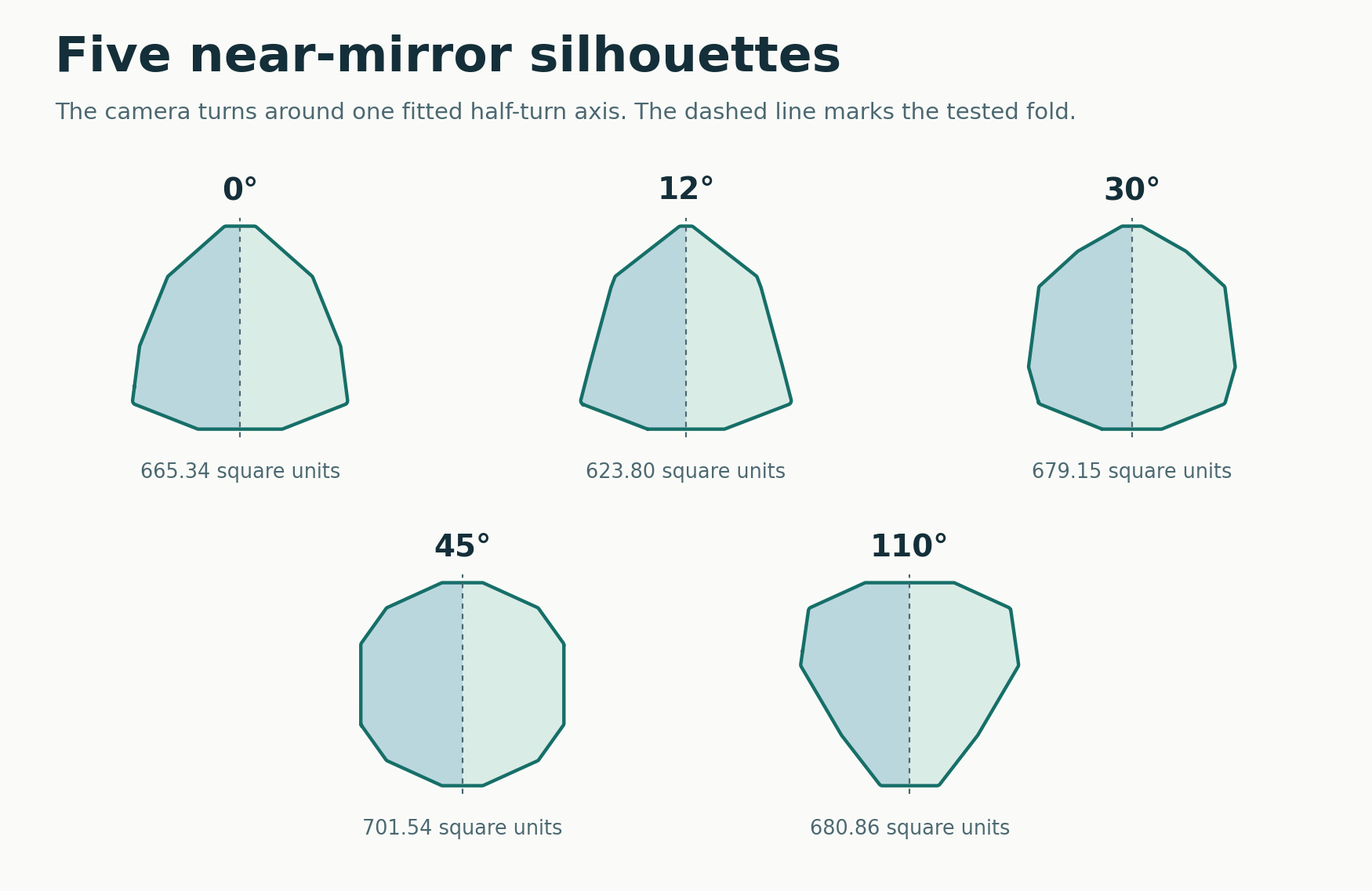
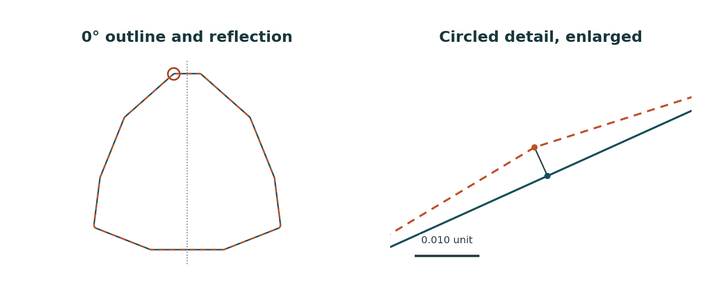
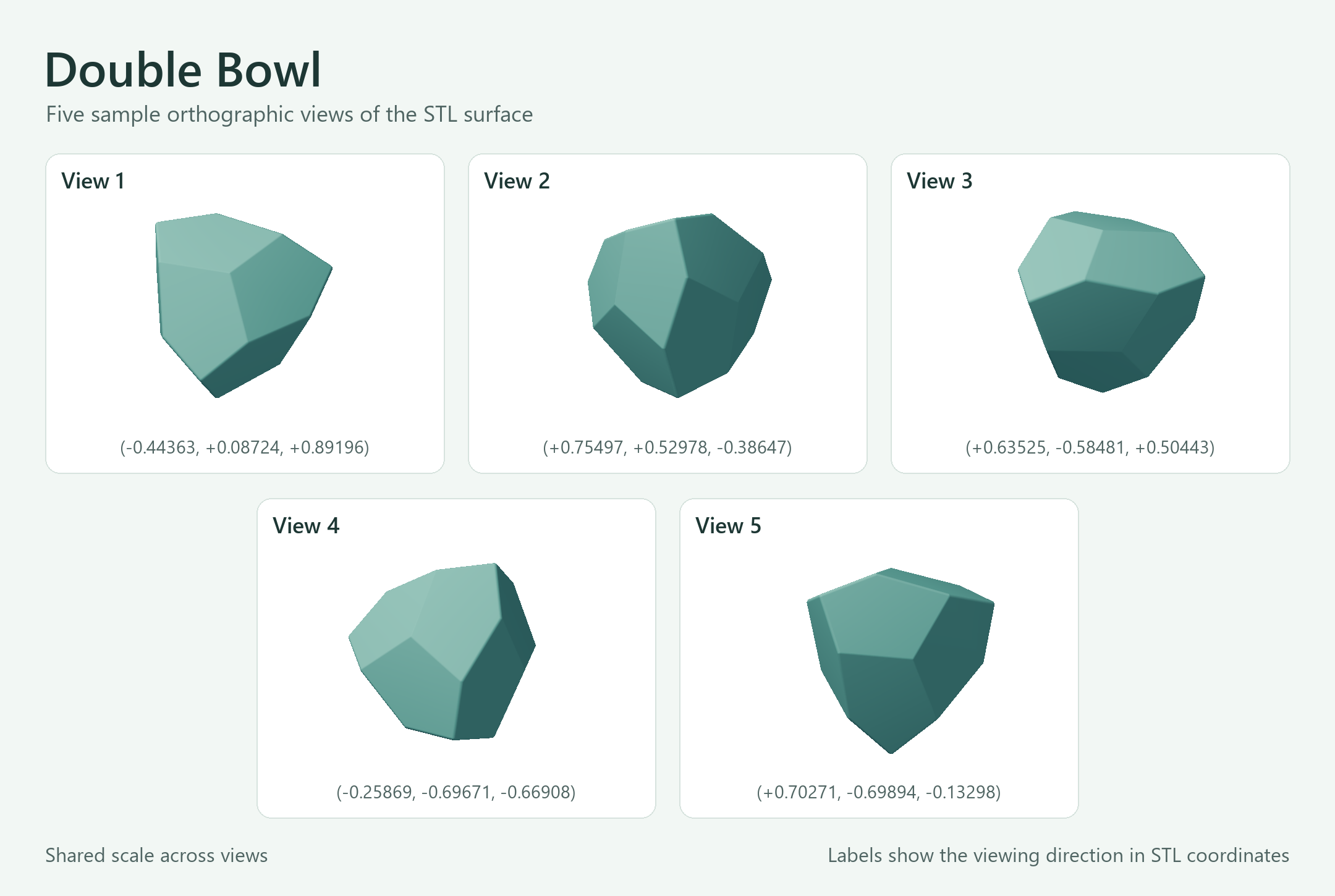
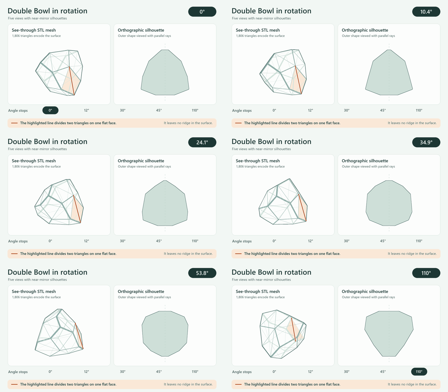
Five near-mirror outlines were checked. The exact contour count across all angles remains open.
Compare the edge sets
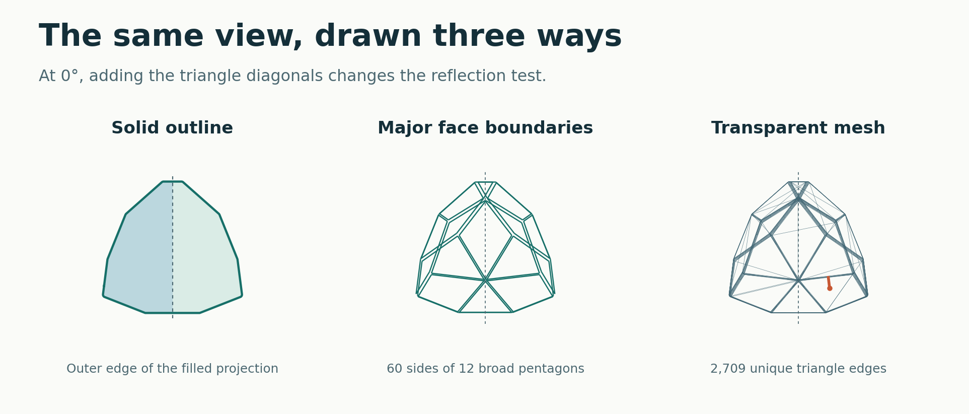
The 60 broad-face sides match their half-turned partners to within 0.000072 length unit. The complete 2,709-edge triangle grid has gaps of about 1.77 to 2.47 units in the five views. A separate turn near +X reduced the grid gap to about 1.33 units.
Read the model’s scale
The STL records 1,806 triangles and 905 vertices on a closed surface. Its coordinate format leaves physical units unspecified, so lengths and areas are given in file units and squared file units.
Five camera turns and what the exact test covers
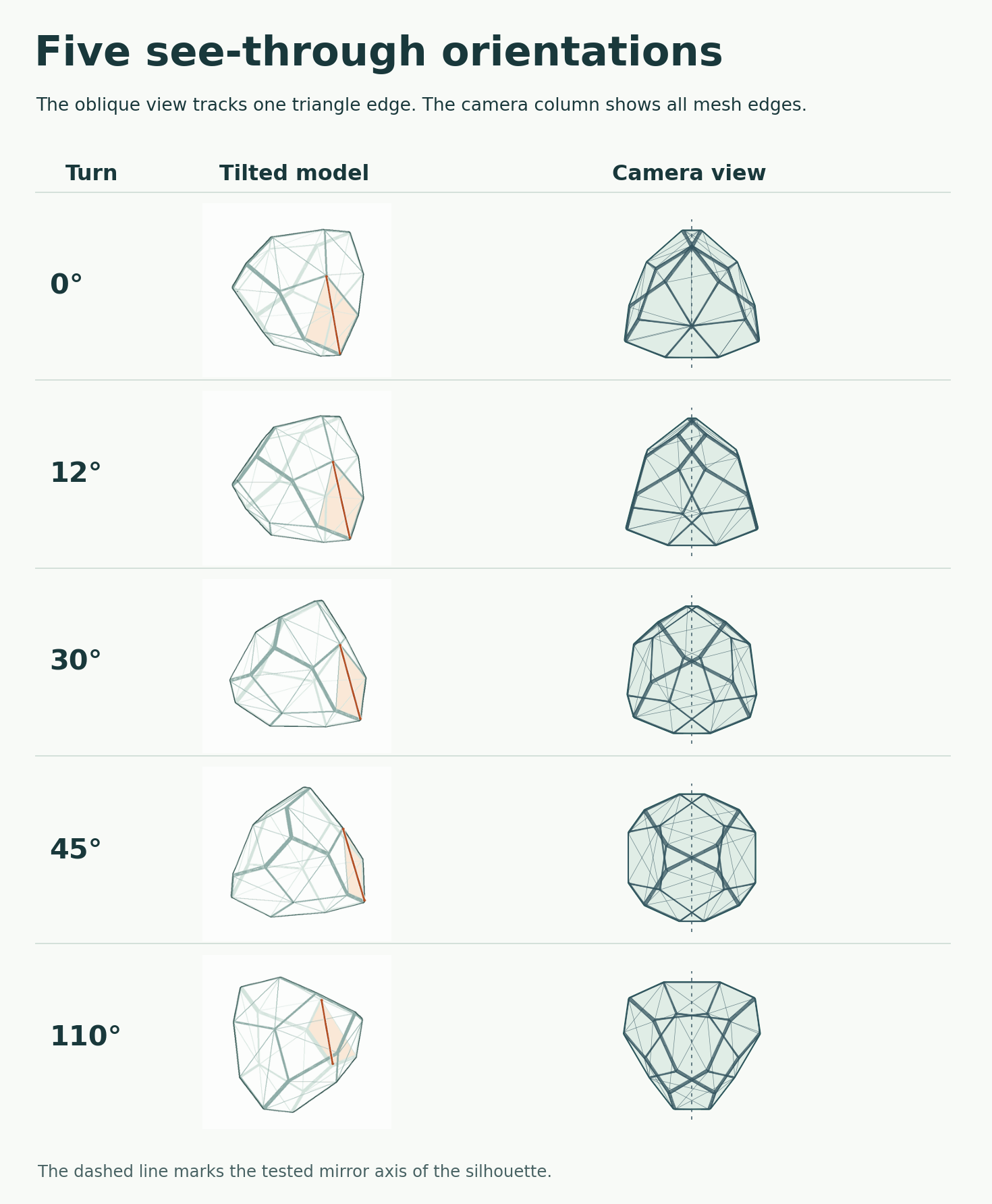
The screen-up axis is approximately a = (0.68472164, 0.44462567, −0.57746367). Project +Z onto the plane perpendicular to a and normalize to obtain the starting sightline n0. The directions are n0 cos θ + (n0 × a) sin θ at 0°, 12°, 30°, 45° and 110°. The screen fold passes through the projected volume centroid.
At each angle, the convex hull of the shadow has a single longest side. A mirror must preserve that side, so only its perpendicular bisector can serve as the fold. An exact calculation sends a hull vertex outside the hull for each candidate fold. All five tested outlines therefore have a small, measurable asymmetry. Exact symmetry at some other camera angle remains open for this mesh.
Independent triangle-union calculations agree on the five areas to five decimal places. The outline gap estimates sample the boundary at most 0.0006 unit apart and add half that spacing to bound the continuous gap. Three approximate half-turn axes support a looser all-angle-on-each-axis-family bound of 0.025 unit.
Why the Double Bowl minimum is bounded
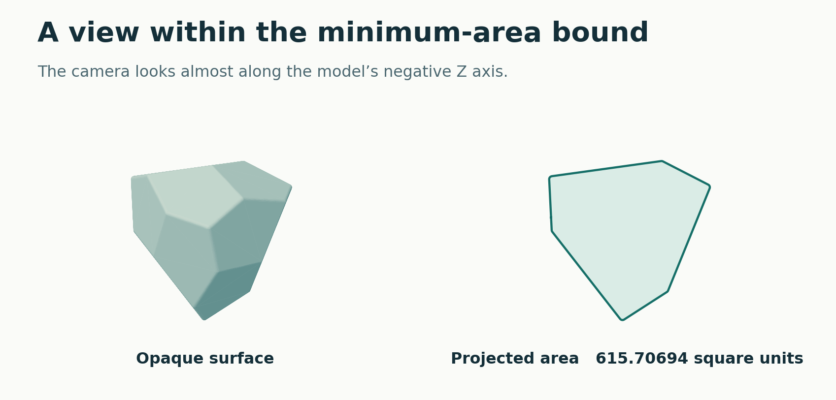
The recorded surface has shallow inward deviations. An inscribed convex solid gives an all-direction lower bound for the mesh shadow. Its supporting planes reduce the lower-bound calculation to 921,381 sightlines from plane-normal pairs. A projected convex outer hull at a tested direction gives a separate upper bound.
The global area lies between 615.689655 and 615.707095 square units. The best tested mesh direction is approximately (0.00000002, −0.000257887, −0.999999967), or its opposite. The exact minimizing direction remains unresolved.
Lesson in text
One sample of five directions gives five profiles. The orange line divides two triangles within one flat face. As the camera turns, its projection changes with the other mesh lines.
At the 12° stop the outline misses its reflection by about 0.005 unit. The full grid misses by about 2.08 units. The smallest shadow area rounds to 615.7 square units on the file’s coordinate scale.
Other solids
Apply the same tests to three different shapes.
Pentagonal icositetrahedron
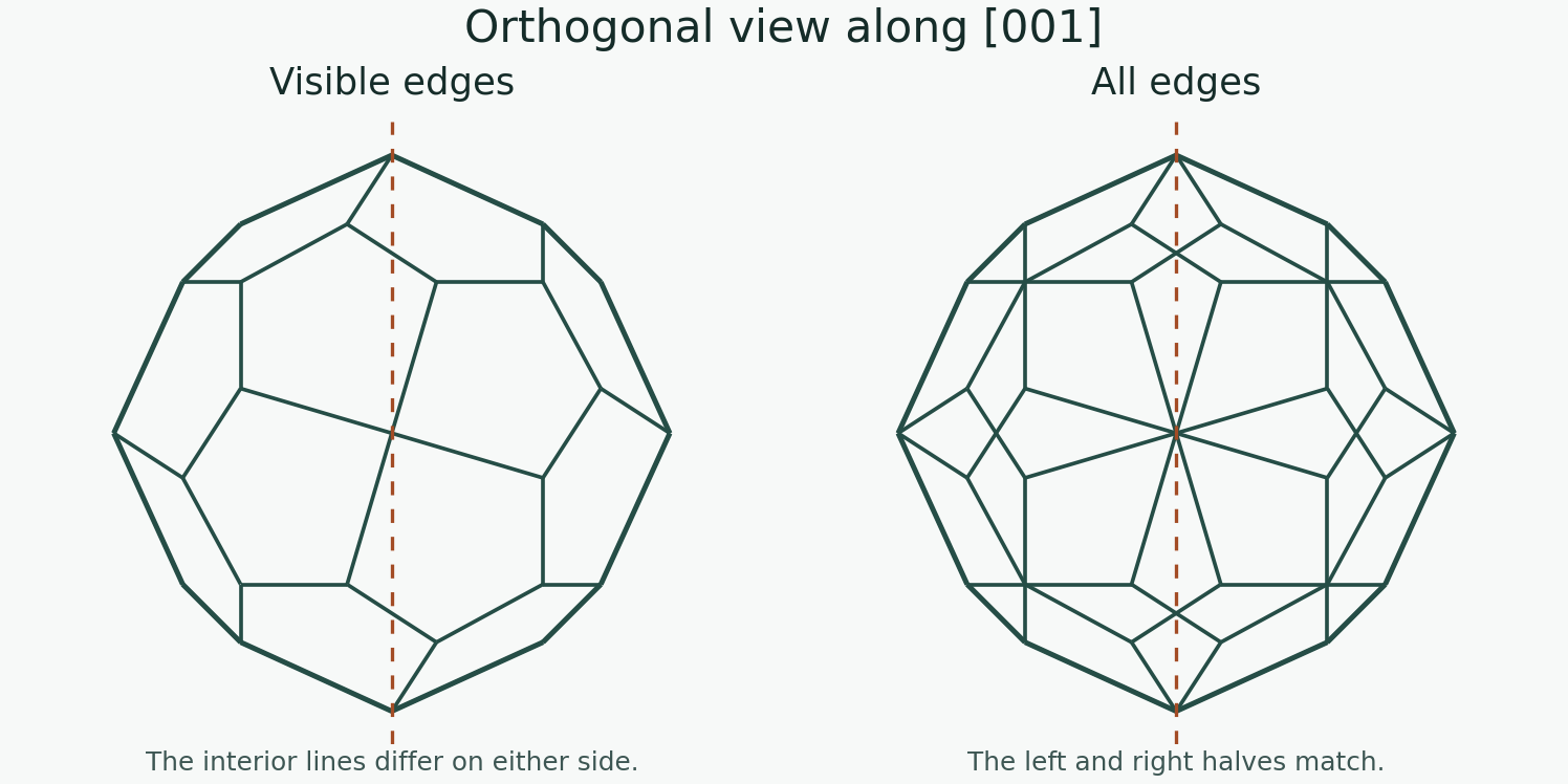
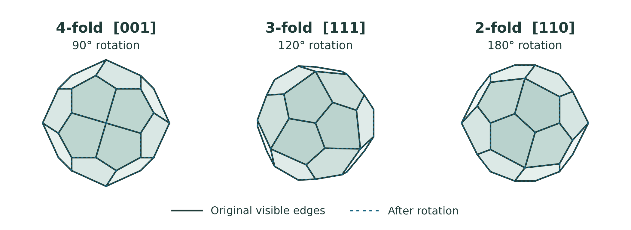
In the [001] direction of this standard chiral solid, the outline and complete wireframe agree with their reflection across the marked fold. The visible interior edges give a different fold result. Rotating the drawings by 90°, 120° and 180° reproduces the projected patterns along [001], [111] and [110], respectively.
Eight-faced STEP model
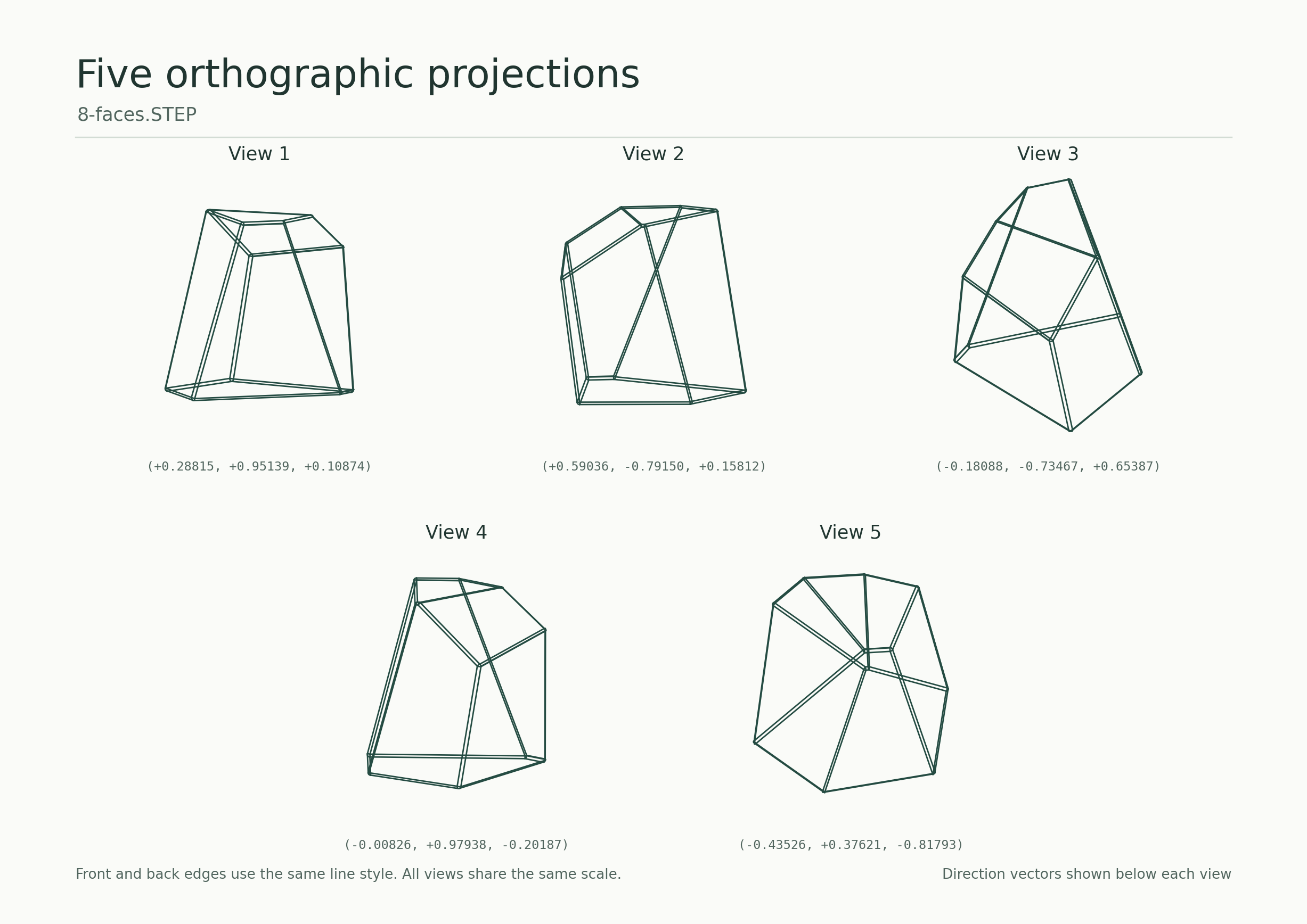
Eight planar faces join through rounded transitions. Its 39 line edges and 45 circular arcs give 12 circle-center groups. The certificate checks 140,152 possible pairings and the neighborhoods of 66 overlap directions, ruling out an exact mirror of the complete wireframe. Its silhouette remains a separate question.
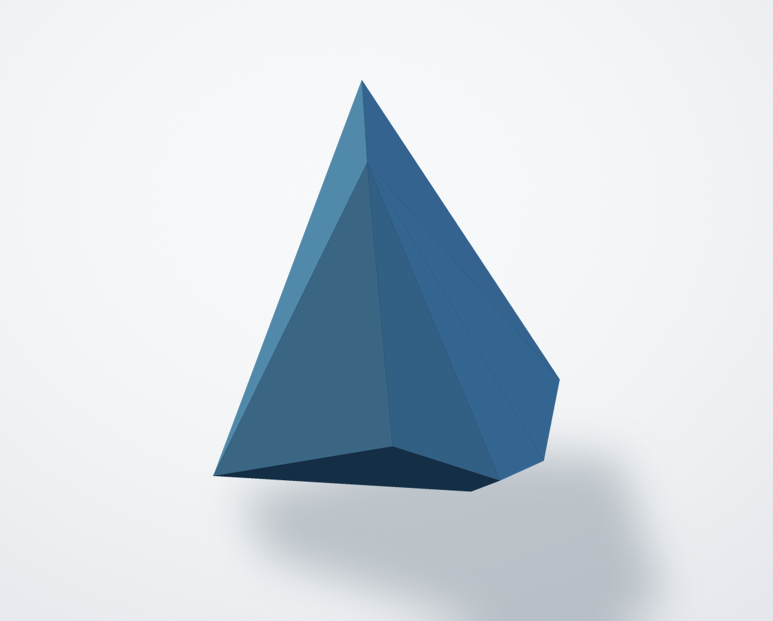
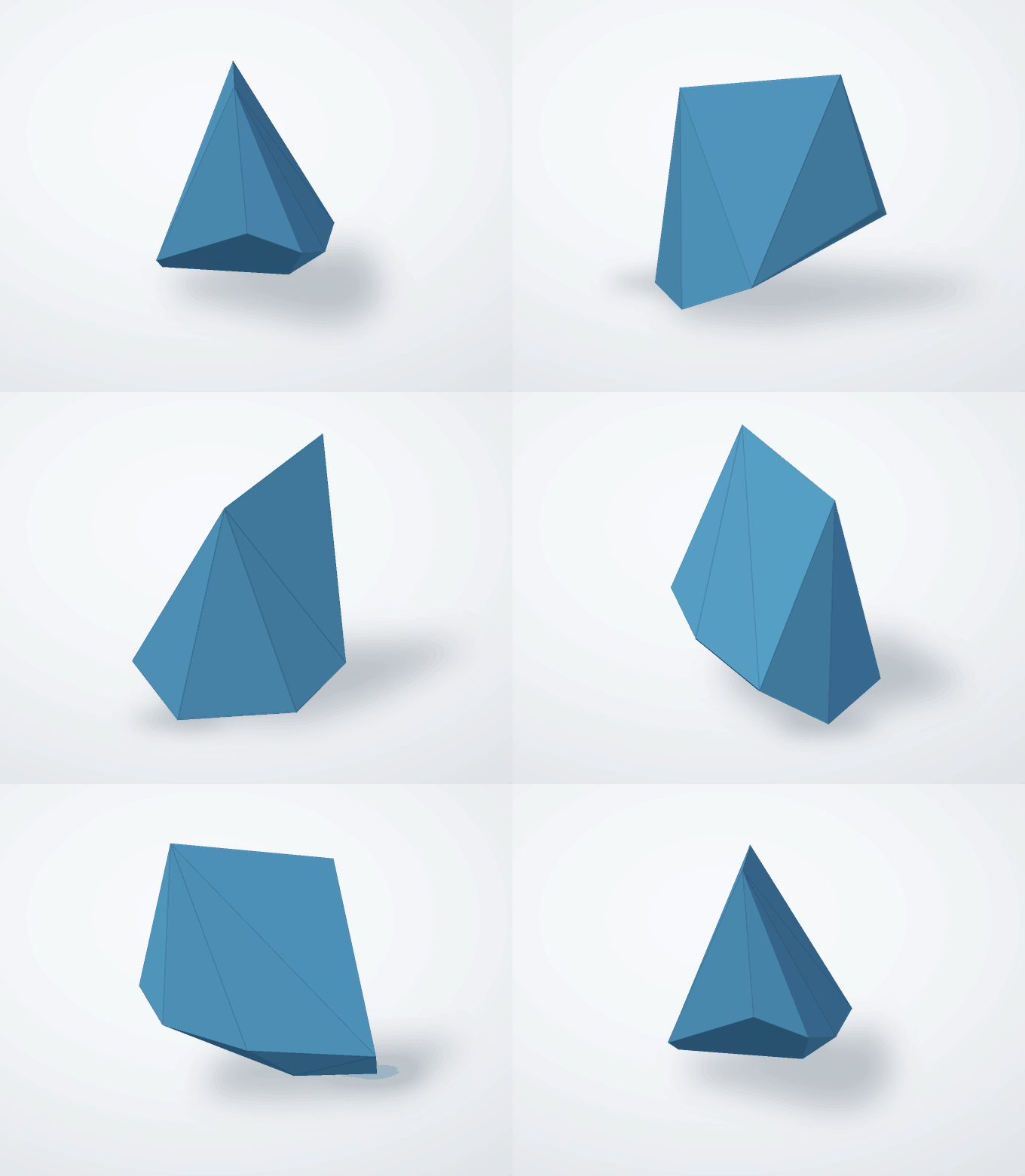
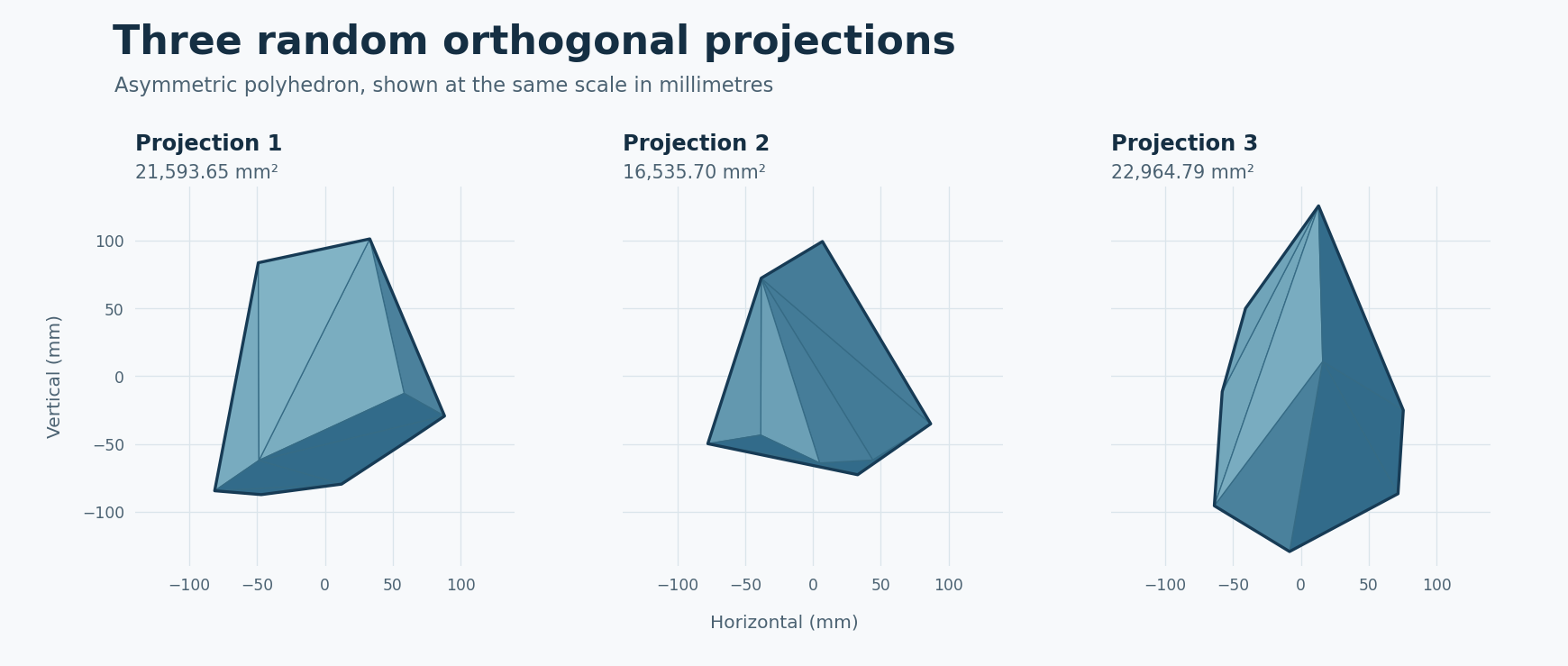
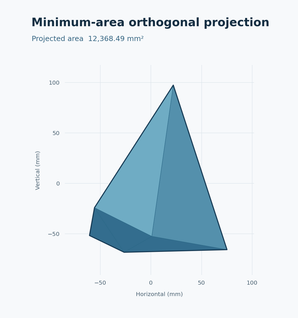
Constructed asymmetric polyhedron
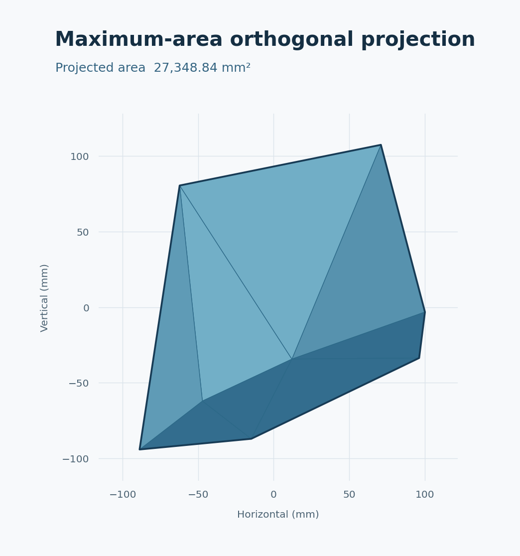
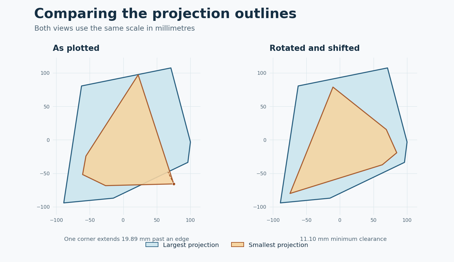
This separate convex example has 10 vertices and 16 triangular faces. Its extreme shadow areas are about 12,368.5 mm² and 27,348.8 mm². Drag in the viewer, choose an extreme, or use the arrow keys while a control is focused. The area readout uses the convex surface formula.
Study library
Read the reports, replay the lessons, and reproduce the checks.
Illustrated reports
Verification files
- Cube wireframe certificate (Python)
- Eight-faced wireframe certificate (Python)
- Double Bowl verification bundle (ZIP)
- Double Bowl mirror checks (Python)
- Double Bowl area bounds (Python)
Run each script with its corresponding source STEP or STL as the command-line argument. The two STEP scripts use Python’s standard library. The Double Bowl bundle uses NumPy and SciPy.